BricsCAD® V26
New capabilities to accelerate the design-to-production process
Learn how this version helps users working in General Design, Manufacturing, Building Subcontracting, and Land Surveying. 60+ additional features for the fastest path from initial design to complete and accurate production drawings.
Navigation tool to easily select the desired position on the cube and dynamically reposition a preset view.
Consistent notifications, offering a simple, clear pop-up for in-product warnings and updates.
Uniformed log in for simplified browser authentication and consistency across tools.
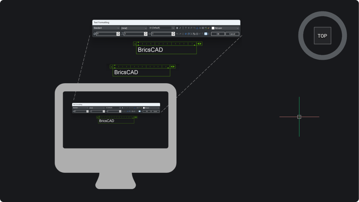
Text, panels, and dialogs now scale more accurately, with increased support for fractional scaling and diverse monitor setups.
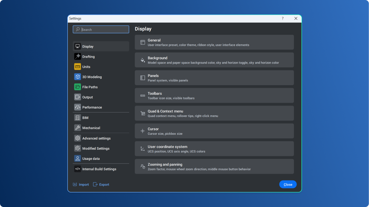
Intuitive, easy process to configure and personalize BricsCAD through the Settings dialog box.
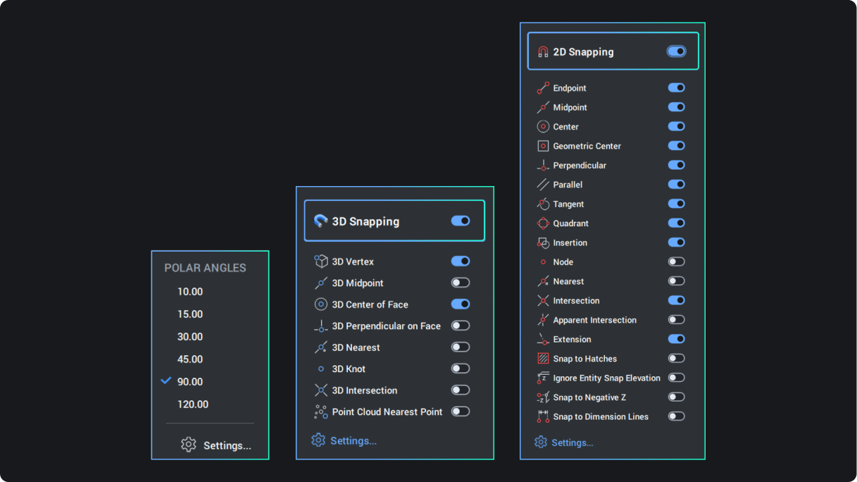
Interface text and graphics in BricsCAD now offer better visibility.
A new launcher to easily find the workspace you need and get started quickly.
Create Dynamic Blocks within BricsCAD (available only for users outside the United States).
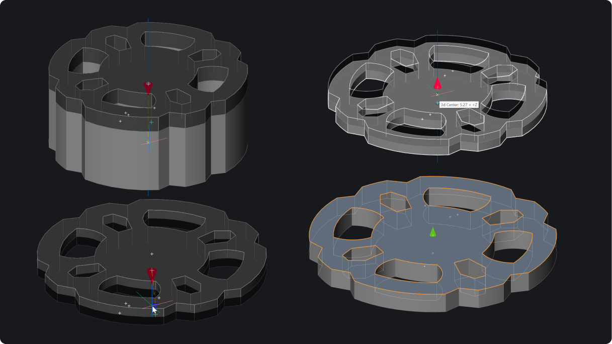
Adjust the size and form of primitive solids and polysolids with 3D manipulation grips for fast freeform editing.
Fillet or chamfer can be applied to all edges of a selected 3D solid in single click when solid option is selected.
Change the drawing units and related settings, like insertion scale and precision, through the command line (-DWGUNITS).
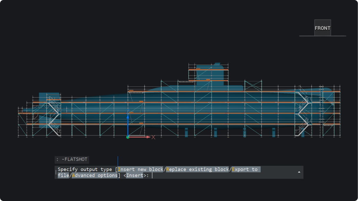
Create 2D block representation of 3D solid geometry based on current view, through the command line or in unattended script (-FLATSHOT).
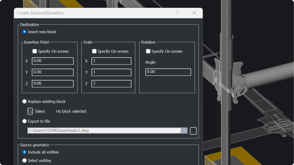
Generate a 2D section block from a section plane of a 3D model, either through the command line or in unattended script (-SECTIONPLANETOBLOCK).
Import, edit, and manage point clouds with thumbnails and search for quick dataset access.
Reverse the direction of lines, polylines, splines, and helixes, making it easier to read text where directionality matters.
Repair open boundaries of surfaces with continuity control to create solids from mesh data (SURFPATCH).

Added user feedback when scaling or rotating solid bodies, making the commands predictable in the graphics window.

Geographic Location dialog box offers now offers a simplified user experience.

Sets or updates the geographic location of the drawing when running through the command line or in unattended script (-GEO/-GEOGRAPHICLOCATION).
Consistency within commands for simplified keyboard input, making design work easy.
Quickly edit geometric properties of 3D solids through the properties panel with dynamic feedback.

New criteria for font substitution introduced for default.fmp and fontalt.fmp files.
Import and export geospatial data with support for industry standard Geographic Markup Language (.GML) enabling consistent collaboration.
Generate Civil Points on objects, grids, or by converting CAD points and blocks for accurate,
efficient site modeling, easily and simply.

Unified user interface for insertion of all block types in BricsCAD, simplifying the user experience.
Quickly find and manage blocks in large drawings, making it easy to identify which blocks are being used and reused.
Edit parameters and actions of Dynamic Blocks to ensure seamless workflow compatibility in a mixed block environment (available only for users outside the United States).
Added functionality to QSELECT command. Select multiple entities when defining the filter.
Determines whether a preview for TRIM and EXTEND commands is shown and can be enabled or disabled by the user.
Advanced classification of edge features in sheet metal, with adjustable extrusion depth for better recognition.
Match georeferenced locations across assets for absolute precision during model federation.
Import IFC models as reference geometry, seperated from the model’s native geometry.

Classify entities according to the IFC4x3 classification structure (BIMCLASSIFY). Export models to IFC4x3, for better alignment with plant and infrastructure projects.
Intuitive UI to apply filters, query data, and manage results. Inspect and delete interferences
by isolating them in model space.
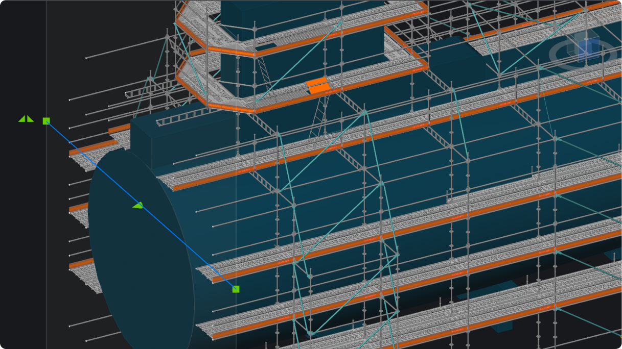
Increased precision when sectioning models with adjustable grips. Change the section type and
depth from the properties panel.
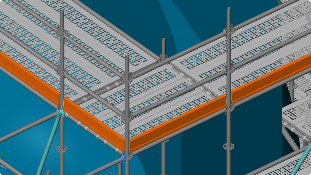
Attribute positions, orientations, and property changes are automatically synchronized when
related parameters are modified.
Run Blockify within the Create Block Definition dialog box. Create new block definitions and
check for existing blocks available for reuse.
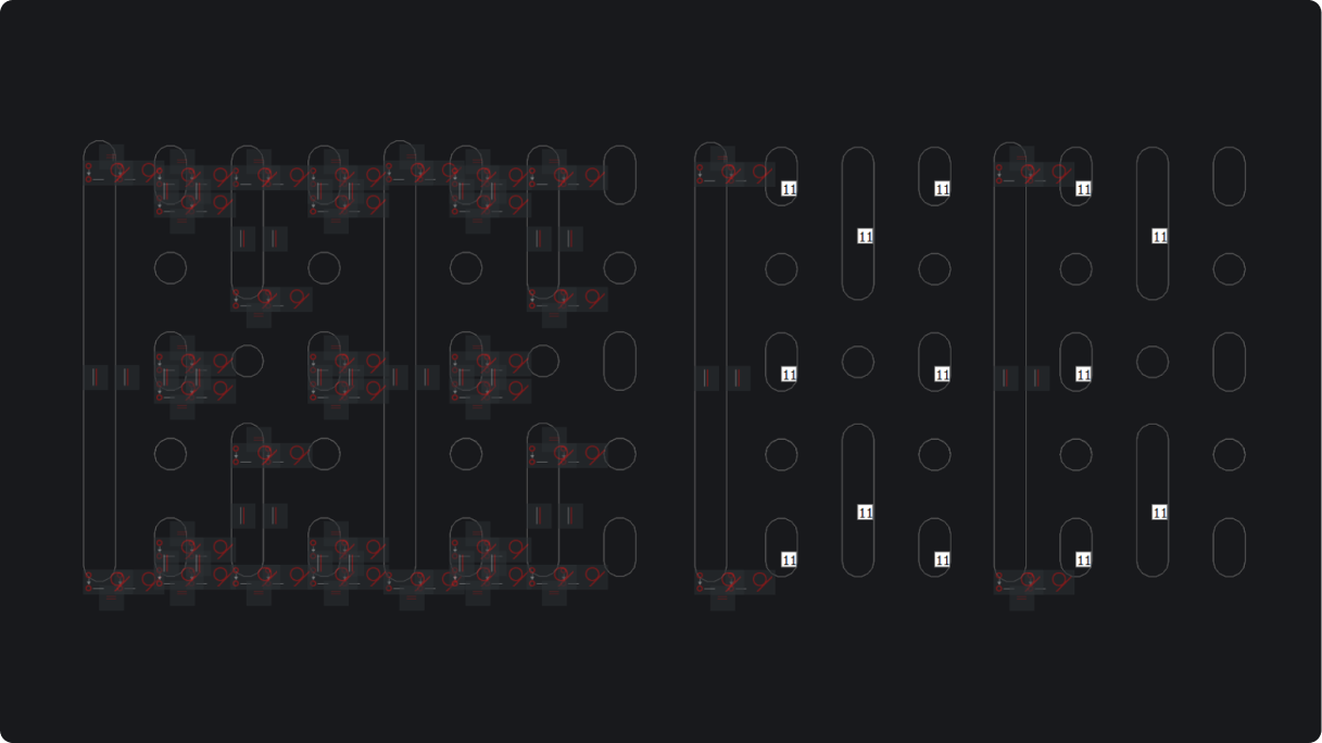
Group symbols to boost performance and clarity in complex drawings.
Highlight the outer shape of point clouds with the new Outline filter for clearer visualization.
Edit 2D FEA objects with fewer clicks. View reaction forces, reuse setups, and zoom-highlight
for faster analysis.
Work efficiently across users and teams with better access to shared project data, like spatial locations and compositions.
Classify project data to be more closely aligned with industry standard classification schemas.
Create detailed geometry and embed needed component information with BIM blocks,
or easily convert existing blocks.
View a sliced section of a 3D model within a specified boundary with editable thickness and offset position.
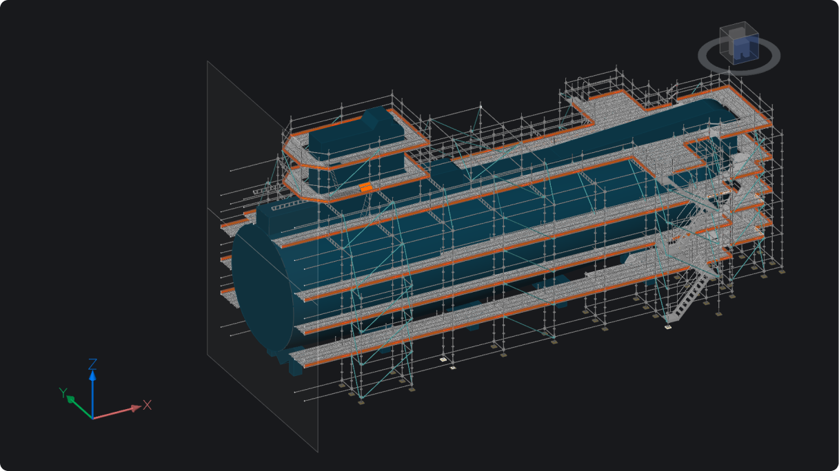
Ability to toggle on and off the display of section planes within 3D model view based on section type.
Measure 2D and 3D distances, radii, angles, areas, and volumes (MEASUREGEOM). Results appear in the command prompt and dynamic tooltip.
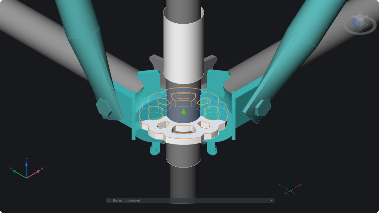
Easier dynamic manipulation of section cuts through 3D solids using intuitive grips.
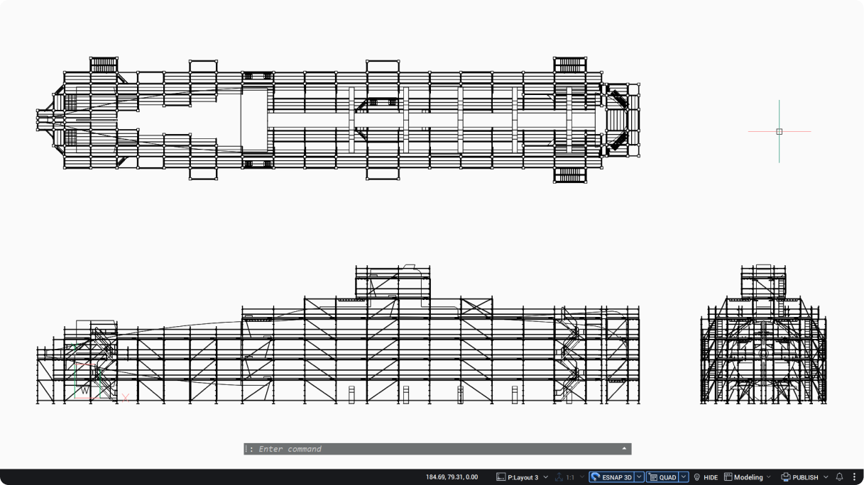
Continue working while generating additional drawing views, improving drafting efficiency.
Easily trace polylines over point clouds with one click per segment for fast, accurate linework (POINTCLOUDTRACE).
New functionality added to MLEADER: press and hold Shift to add temporary ortho alignment for easier leader placement.
Smarter commands and advanced UI make power dimensioning faster and more accurate.
Save time with automated chamfer dimensions. Select the chamfer and edges to instantly create two clear linear measurements.
Quickly apply advanced weld symbols with full property control from a unified panel.
Quickly cycle and locate through parts in drawings, combining zoom and highlight into one efficient command.
Generate orthographic images and auto-detect lines from point clouds using a section plane for precise results.

Easily generate and incorporate accurate volume reports for cut and fill analysis.
Automatically assign point styles and layers based on point codes for faster drafting.
Add and customize civil labels, now including automated GIS data attributes, for smarter, easier, faster annotation.

Slope and elevation analysis with custom ranges, colors, and legends for clear surface visualization.
Easily create Civil Sections and Section Views along any Alignment or String for detailed design insights, in bulk and at scale.